Reduce Profile Development Time and Cost
What was the problem?
Time consuming and costly profile development process
The profile extrusion die manufacturer went through a long and expensive process to develop a die for this profile. It was balanced by land (length adjustment/relief) which required manual filing of the die plates in order to achieve an acceptable product at an acceptable rate. This process took a few weeks! After a few months of operation, and complaints from the user that the die was very sensitive to line speed and could not be operated at a higher rate, they were requested to manufacture a duplicate of the current die (in order to double the production rate). However, since the die was balanced manually, and the modifications were not recorded, it was almost impossible to reproduce the same final design. The die manufacturer wanted to find a better, faster (more efficient) way to develop their profile dies.
What was the root cause?
Development by trial-and-error and cross flows!
The following image shows the velocity contours at several cross sections along the original die flow channels, as predicted by the VEL™ Profile Die module.
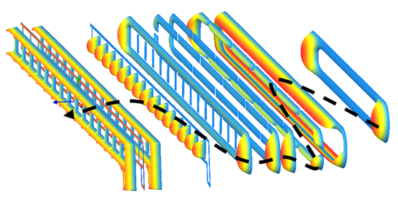
The above profile extrusion die was developed using the traditional, but in-efficient, trial-and-error method. In this method, die was first designed and manufactured without any scientific flow calculations. After the first trial, the profile was measured and the die was then modified by adjusting(relieving) the land in the final plate, in an effort to balance the flow. This introduced “cross-flows” into the design. After the modifications were made, the die was run again and the profile was measured. This process is typically repeated, many times, until the extruded profile dimensions are acceptable. No records are typically kept of the modifications made during this procedure.
How it was solved?
Develop the die using COMPUPLAST® Cross-Flow Minimization method!™
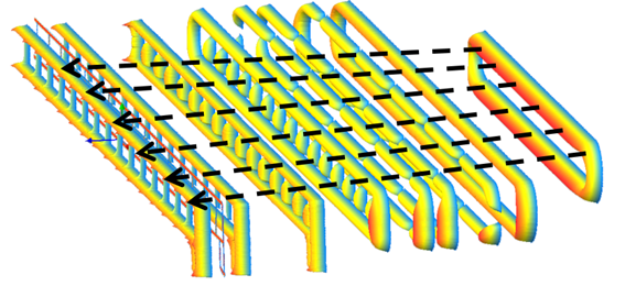
COMPUPLAST® took the original design of the die, before any modifications were made to it, and analysed it using the VEL™ Profile Die Module. The die was found to be very “unbalanced” with respect to the required flow distribution. Then, using the COMPUPLAST® Cross Flow Minimization Method™ we ran optimization iterations/simulations on the computer until the flow was balanced and, the cross-flows were minimized. The following image shows the velocity contours at several cross sections along the optimized die flow channels.
The die was built using the optimized design. The customer was able to develop (tune-in) the new die in a few hours (as opposed to weeks), as most of the trial-and-error was performed with the simulation on the computer. Since all the modifications were recorded, the customer would have been able to easily duplicate the die whenever required. The die was also less sensitive to process changes and could be operated at a much higher line speed.
Bottom Line
Thanks to the VEL™ Profile Die Module and the COMPUPLAST® Cross Flow Minimization Method™, the customer was able to save thousands of dollars on their extrusion die development process and produce better profile extrusion dies.